avrOLED Graphic Generator
I like simple things and simple displays. That is why I lean towards OLED displays and simple pixel displays. The value provided from microcontrollers or single board computers is information, not an over complicated display. OLEDS can display nice, simple graphics for your project however generating an image into a 8 bit header file can be cumbersome.
I wanted my workflow for this to be:
- Design a graphic based on the pixel size of the chosen hardware display
- Create python script that can generate the .h file for my AVR project
Generating the graphic
There are tons of options for generating a BMP. On linux, I settled on using mtpaint which is common software among a number of distros. It easily creates a pixel canvas to a specified size, you can select the palette color, palette size. It even has a feature that allows text to be easily mapped to the display. This enables the user to have different fonts without over complicating it!
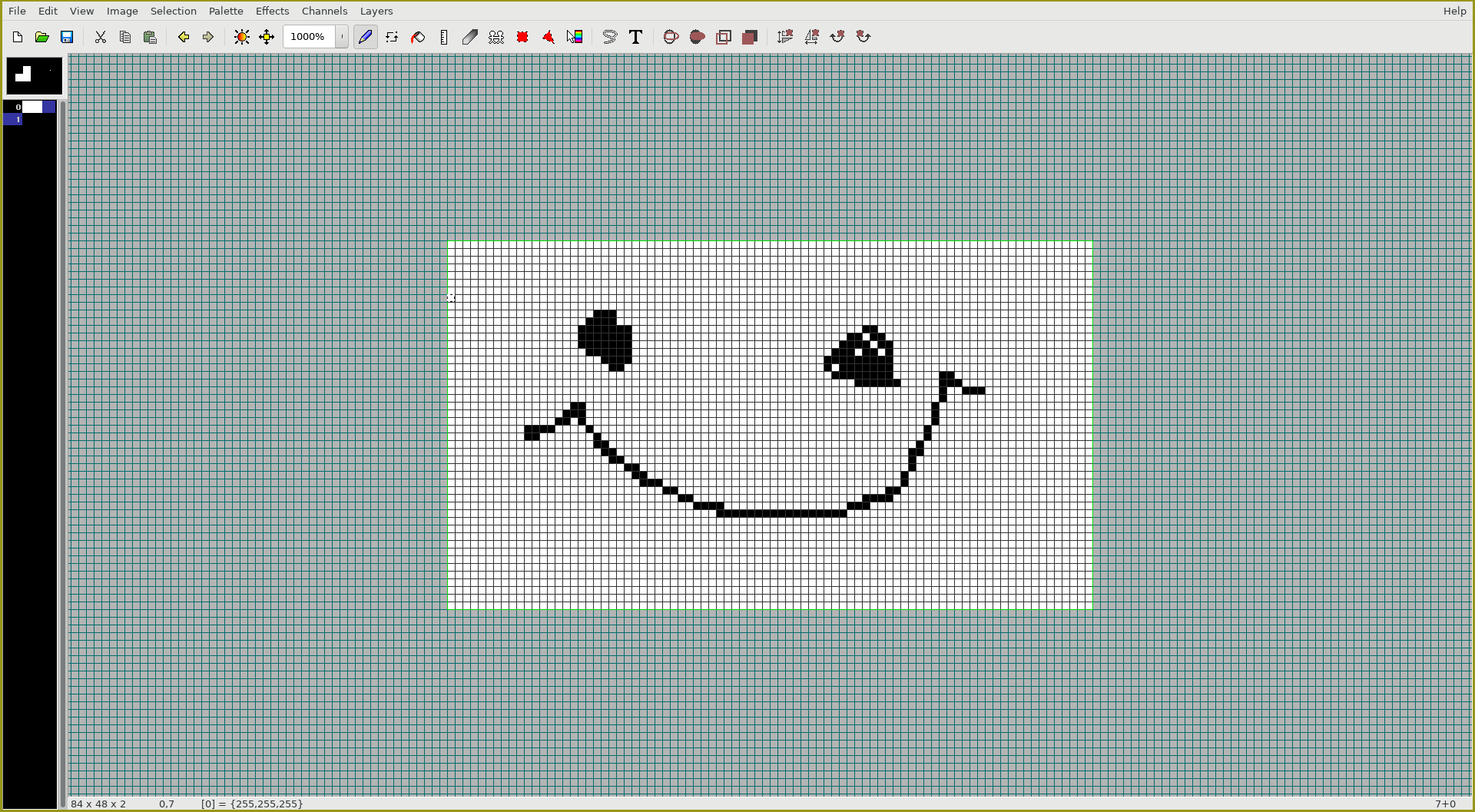
For developing the script, I used the classic Phillips PCD8544 48x84 pixel matrix. This screen was commonly found on Nokia cell phones. My image for the demo looks like chicken scratch but it will do the job here. After saving the image, it was time to figure out how to read this BMP into python and generate a header file.
Understanding Bitmaps
I’m not going to cover the image processing aspect of this but I found the following article Bits to Bitmaps: A simple walkthrough of BMP Image format EXTREMELY insightful. Bitmaps are stored in…BYTES! The file has a bitmap header which contains a bunch of information about the file itself. There is a specific variable that tells you the offset in the bytes to where the raw image data begins.
This was my first time implementing the ‘struct’ library in python but it is pretty slick. It performs conversions between Python values and C structures which is exactly what we need to do. Read a BMP with python and convert those values to C values so the AVR can interpret it.
When you walk through the script, you’ll see a number of variables that are created from reading the values in the header section of the BMP such as image width and height. We’ll use these in the algorithm to create the header file such that this can be scaled to any size pixel display.
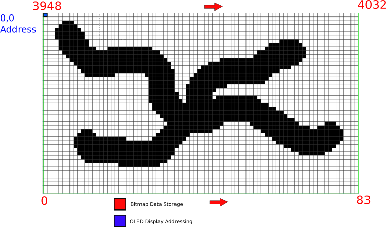
Probably the most important variable is the offset. To cover quickly, the graphic I made was 48x84 and 1 byte is used to store a pixel. In this case it would take 48*84=4032 bytes but the file size is actually larger for the simple reason, it needs to store the the formatting information in the header. If we take the fileSize - offSet, we would get 4032 because that is how many pixels we have and need to store raw data. This can change depending on how the BMP is generated and stored but this fits my workflow which tends to be only 2 colors.
The raw data maps to pixels by beginning at the lower left corner of the image and incrementing to the upper right corner. This is not aligned with our display addressing so there is some work to do.
Formatting for the display
Typically when I use displays with microcontrollers, I’ll use horizontal addressing and the origin begins in the top left of the display. So the pseudo-code would be
- Set cursor to 0,0
- Write 1 byte
- Increment
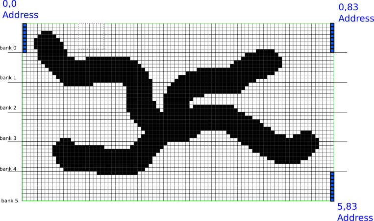
Knowing the width, height, and 8 bit architecture, we are able to increment through the 4032 bytes of raw BMP data just as the AVR would read and write it. This way, the output.h file that is generated can be read straight through with no additional tweaking. The OLED typically receives a single byte to represent 8 pixels. By grouping 8 pixels on this display, we end up with vertical banks. Since the display is 48 pixels high, 48 divided by 8 bits is 6 banks (beginning with 0). When the AVR talks to the pixel display, we need a header file array with 6 * 84 columns = 504 values. That will represent our entire image we designed in pixels.
Therefore when we iterate through the raw BMP data, we need to move vertically and horizontally. It finds the 0,0 origin and goes from 0 to 83 which are the number of columns. This completes the entire bank 0 data. It then shifts to bank 1 and begins on the 0 column, repeating the process. The written output to the .h file is then 0 to 504 on the horizontal addressing scheme for the pixel display.
This script allows me to design a graphic for a display in a GUI then easily convert it to match some common OLED displays I’ve used. GIMP also has a C header exporter but needs some tweaking in my experience to work directly with the AVR. One of the more insightful aspects of this project was the ‘struct’ library in python. This is a great tool to use with other hex data that may come from an AVR project such as dumping EEPROM data, preparing EEPROM data, reading FRAM and bunch of others. I’ll keep ‘struct’ in the back pocket.